ENDFACE TESTING
Made by Promet Optics

Large core/diameter fibers (> 9-50-62.5/125 µm standard telecom fibers) are widely used n the aerospace/defense, sensing, and medical device industries in applications with high power and low bandwidth requirements. Connections using these fibers can utilize an assortment of techniques, but standard connector and termini styles are common. The endface geometry of the connector/termini can be critically important in certain applications, especially in MIL/Aero.
“End face geometry is as important as ever in the aerospace community to ensure low losses and optimum system functionality. It has been agreed by various aerospace committees that we should maintain the tight tolerances for end face geometry and not follow telecom, where the end face geometry requirements have been reduced.”, John Cotterill, Secretary SAE AS-3 Fiber Optics & Applied Photonics Subcommittee.
SAE standard AS-5675 addresses endface geometry for common MIL/Aero fiber diameters; defining the measurement area standards for common aerospace fiber diameters similarity to telecom standards Telcordia GR-326, TIA/EIA 455 and IEC 61300. Using this standard as a baseline, developing appropriate measurement criteria for other fiber diameters is explored here.
When measuring a fiber to a standard like AS-5675, it is essential to define the proper measurement area as called out in the standard. The measurement area is broken down into 3 fitting areas, as shown in below in figure 1.
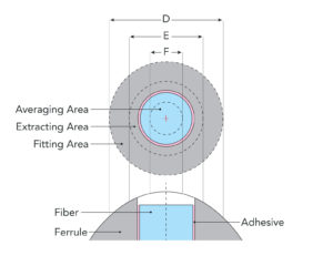
Figure 1: Fitting areas
Fitting area values per AS-5675 are defined in Table 7 below for various fiber diameters.
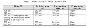
Table 7: AS-5675 Fitting Area Definitions
Custom measurement areas can be defined at the discretion of the user depending on the application requirements. However, keeping consistent with industry standards is commonly desired when ensuring product quality. Using AS-5675, the following equations are 2nd degree polynomial fits to the values Table 7. These equations are one rough approximation method to calculate fitting areas for other diameter fibers.
- Fitting Zone OD = -.0002 (Fiber OD)^2 + 1.028 (Fiber OD) + 127
- Extracting Zone OD = .0002 (Fiber OD)^2 + .923 (Fiber OD) + 21
The averaging area, F, is used to calculate the height of the fiber. Note that they are the same in AS-5675 for all fiber diameters.
Detailed descriptions of how the endface geometry measurement values; radius, fiber height and apex offset; are calculated can be found in TIA/EIA 455-218 and IEC 61300-3- (16, 17, 23)
The endface geometry pass/fail criteria for these measurement areas are defined in AS-5675 for common fiber diameters but individual users can define acceptable criteria for their application through custom measurement configurations.
Imputing custom configurations can be done in FiBO Code, figure 2.
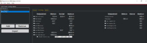
Figure 2. FiBO Code Custom Configuration
As shown in the FiBO Code configuration, the “Minimum” is the Extracting Zone OD value and the “Maximum” is the Fitting Zone OD.
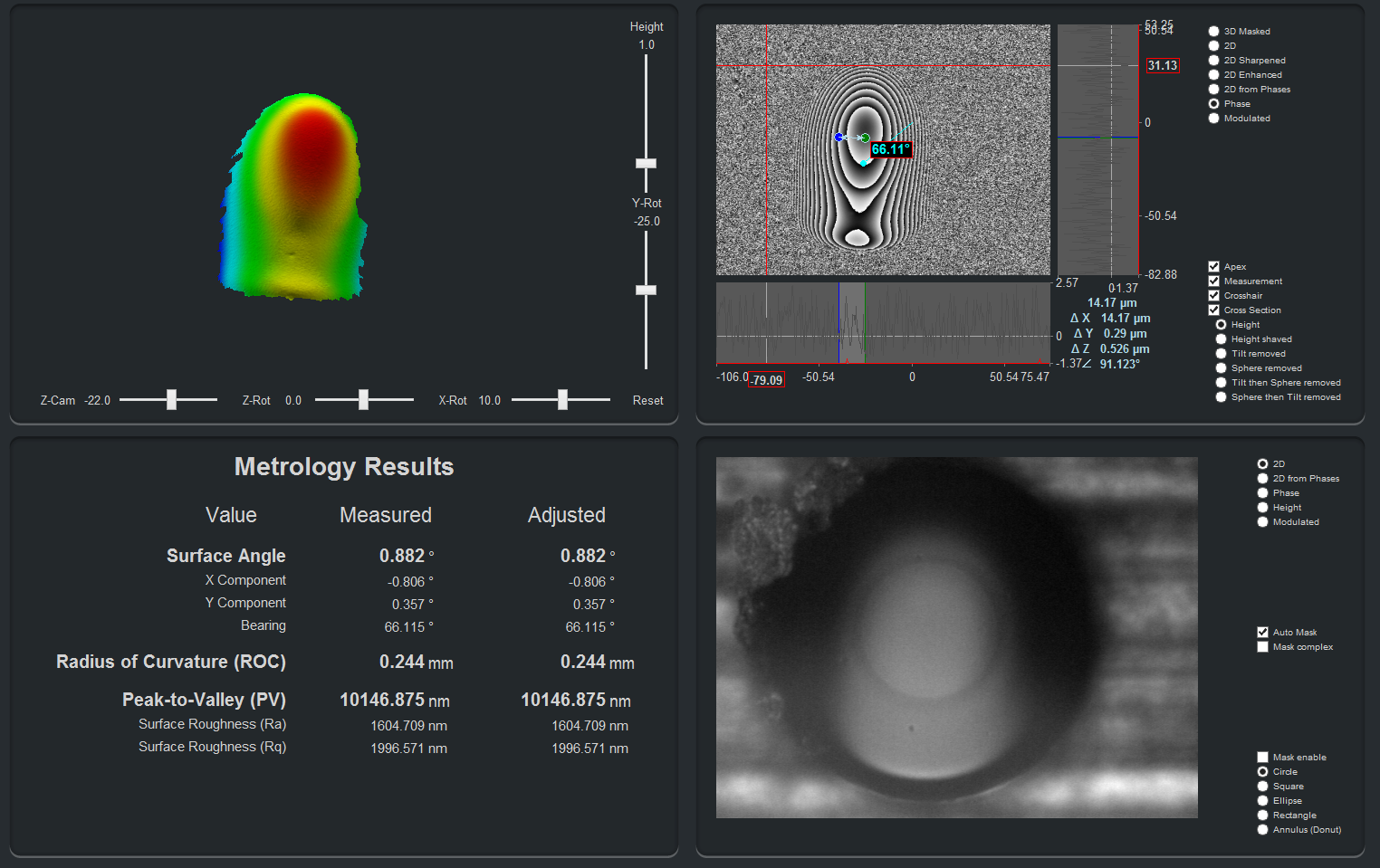
An example of a 400/440 µm fiber with a custom measurement area as measured on a FiBO 300, with ~1000 µm x 800 µm field of view, is shown in Figure 3 and Figure 4.
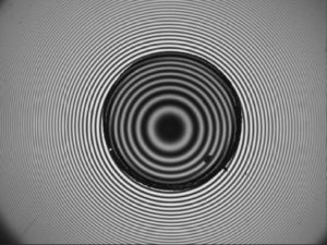
Figure 3: Fringe pattern for 400/440 µm
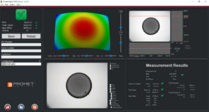
Figure 4: Endface Geometry Results for 400/440 µm
As more and more systems migrate to fiber, the ability for effective QC of non-standard fibers becomes critical. Standards like AS-5675 provide a baseline for applying defined measurement techniques to other fiber core/diameter configurations. In conjuncture with a large FOV interferometer, like the FiBO 300, engineers have the means to inspect non-standard fibers in a reliable and consistent manner.
Table 7 from SAE standard AS-5675 “Characterization and Requirements for New Aerospace Fiber Optic Cable Assemblies – Jumpers, End Face Geometry, Link Loss Measurement, and Inspection, 2012-05
Special thanks to John Cotterill, JSC Aeroptics Ltd.; Secretary, SAE AS-3 Fiber Optics & Applied Photonics; Chairman, UK BSI ACE6/10 Aerospace Fibre Optic Systems and Equipment, for his contributions to this post.