ENDFACE TESTING
Made by Promet Optics

This is the fourth of a four-part post from the white paper entitled “Variation in Linear Apex Offset Measurements of Angled Fiber Optic Connectors”.
Reference Planes
To address possible error source #3 listed above, it is apparent there is a need to have very well defined reference planes for both Key Angle and Polish Angle values in the measurement system. The theoretical planes used as the reference for the Polish Angle and Key Angle values can be described as follows:
The Polish Angle reference plane is a plane normal to the optical axis and passing through the origin (i.e. center of the fiber).
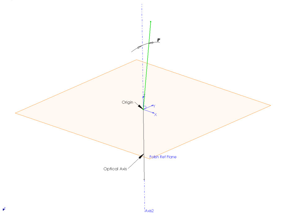
Fig. 21: Polish Angle Reference Plane
The Key Angle reference plane is a plane normal to the Polish Angle reference plane and passing through the origin.
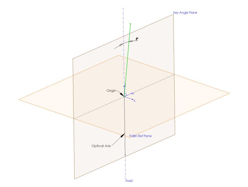
Fig. 22: Key Angle Reference Plane
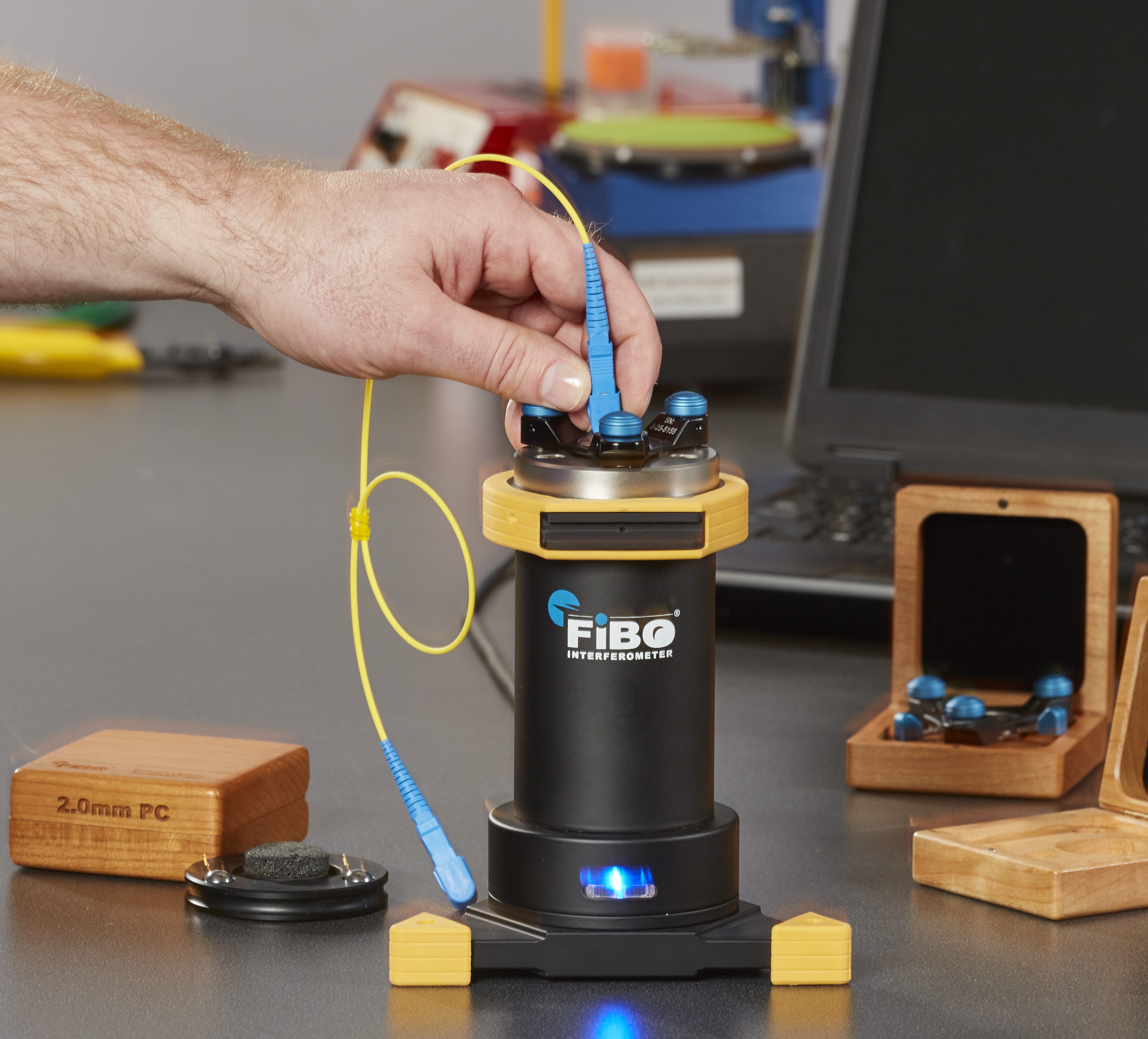
Although these reference planes are clearly defined in geometrical space, it is challenging to effectively transfer these reference planes to real world mechanical systems. One of the most effective methods of accurately mechanically defining theoretical orientation planes and axis is through the use of symmetric, kinematically defined contact points. The FiBO® Interferometer implements this method to clearly define theoretical reference planes used in calculating Linear Apex Offset measurements to achieve absolute accuracy.
A 3-ball (6 contact point) kinematic arrangement in conjunction with interchangeable kinematic adapters is used to define a nominal local coordinate system at the point of the connector endface. This arrangement is mechanically reproducible to within ± 1 microns corresponding to about ± 15 arc seconds of angular error for the reference planes used to calculate Linear Apex Offset.
The reference plane for the Polish Angle value is mechanically defined as follows:
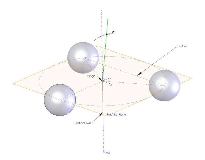
Fig. 23: Mechanically defining the Polish Angle reference plane with a 3-ball kinematic arrangement
The plane through the center of the three balls is determined by indexing the kinematic interface assembly and taking three measurements at 120 degree clocking angles. The resulting three points define the Polish Angle reference plane with the Origin located at the center of the three-point circle. The X-Axis of the Polish Angle plane is defined as a line going through the centers of two of the balls.
The reference plane for the Key Angle value is defined as a plane which is normal to both the Polish Angle reference plane and the X-Axis of the Polish Angle reference plane and passes through the Origin.
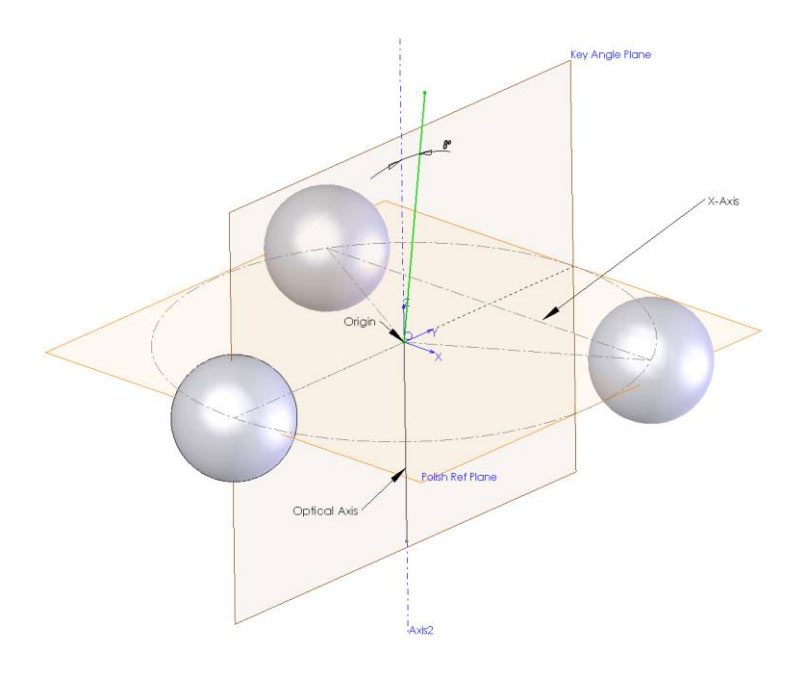
Fig. 24: Key Angle reference plane with a 3-ball kinematic arrangement
The location of the Key Angle reference plane is actually determined using a CMM method and the three reference balls.
Once both the Polish Angle and Key Angle reference planes are mechanically defined, the kinematic adapters can be actively aligned to the desired accuracy using proprietary alignment methods. The three ball kinematic interface ensures a very high-level of repeatability and allows for interchangeability between different interferometer systems.
Minimizing KOA Errors when Measuring
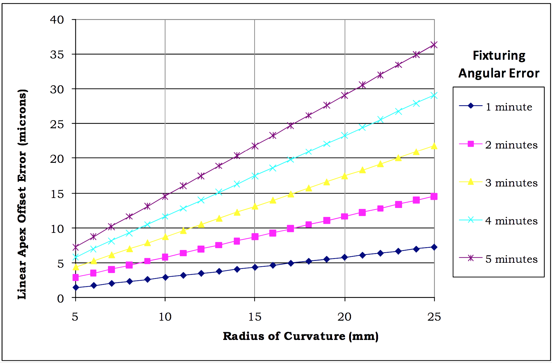
In light of the relationship between the KOA and the resulting excess Apex offset, it is obvious that the measurement of Linear Apex Offset in APC connectors is not straightforward. Rotating the APC ferrule in the connector body or rotating the connector body inside a loose keyway can result in Linear Apex Offset measurements that vary by tens of microns, or more, for the same connector.
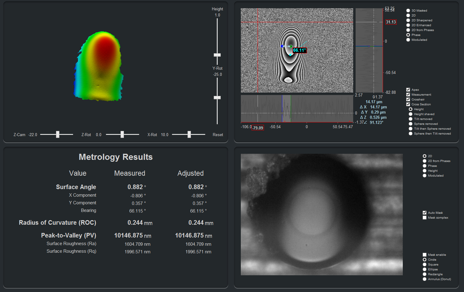
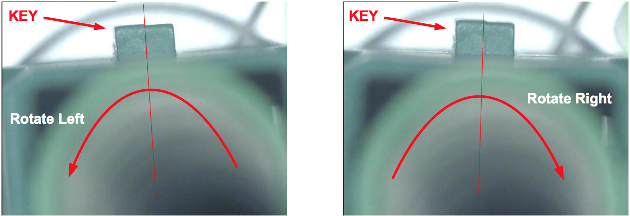
Minimizing the error due to KOA error reduces measured Linear Apex Offset and leaves Linear Apex Offset due to the Polish Angle error. KOA is minimized when the interferometric circular fringes are centered on the X-axis of the image, for example:
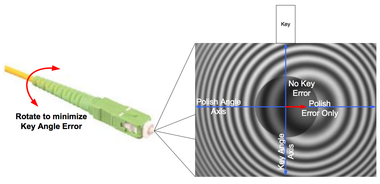
Fig. 25: Interferometric image of APC ferrule rotated to achieve minimum KOA error
This manual rotation to minimize the KOA effect can be achieved while viewing the live interferometric image. This may be a philosophically unsatisfactory method for measuring Linear Apex Offset, but if there is intentionally designed looseness between the ferrule and the connector body, then the Linear Apex Offset will vary as the ferrule rotates and this may be the only way to minimize the variation. This method of measurement is also not compliant with any industry standards documents and should only be used only in very specific situations.
Summary
There is a direct relationship between Linear Apex Offset and Key Orientation Angle error in APC fiber optic connector endface measurements. The theoretical relationship between Linear Apex Offset error, Key Orientation Angle and Radius of Curvature was derived theoretically, experimentally verified and results plotted. This error can result from intentional looseness between the connector body and the ferrule, key and keyway construction and tolerance, as well as the fixturing of the connector while being measured. To minimize the measurement system errors, it is important to clearly define the reference planes, and relate them to mechanical reference points. A symmetric kinematic arrangement is a very reproducible and accurate method of mechanically defining these planes. The rotation errors inherent in APC connectors can lead to large variations in Linear Apex Offset, but these effects can be minimized by manually rotating the Key Angle Offset when making measurements.