ENDFACE TESTING
Made by Promet Optics

This is the second of a four-part post from the white paper entitled “Variation in Linear Apex Offset Measurements of Angled Fiber Optic Connectors”. We will define Linear and Angular Apex Offset and explore how ferrule rotation in APC connectors can result in erroneous apex offset measurements.
Rotation of a PC Ferrule
If a PC ferrule is perfectly rotated about its axis (green dashed line in the following diagram) the direction of the Linear Apex Offset changes, but its magnitude stays the same.
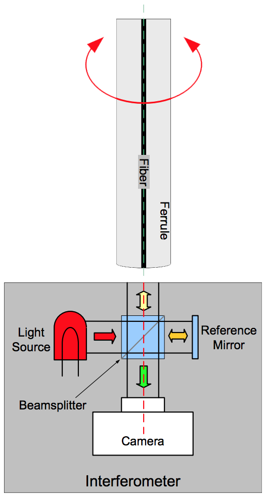
Fig. 8: PC ferrule rotation indicated by red arrow
This rotation is illustrated in the following fringe images where the ferrule was rotated in 60 degree steps:
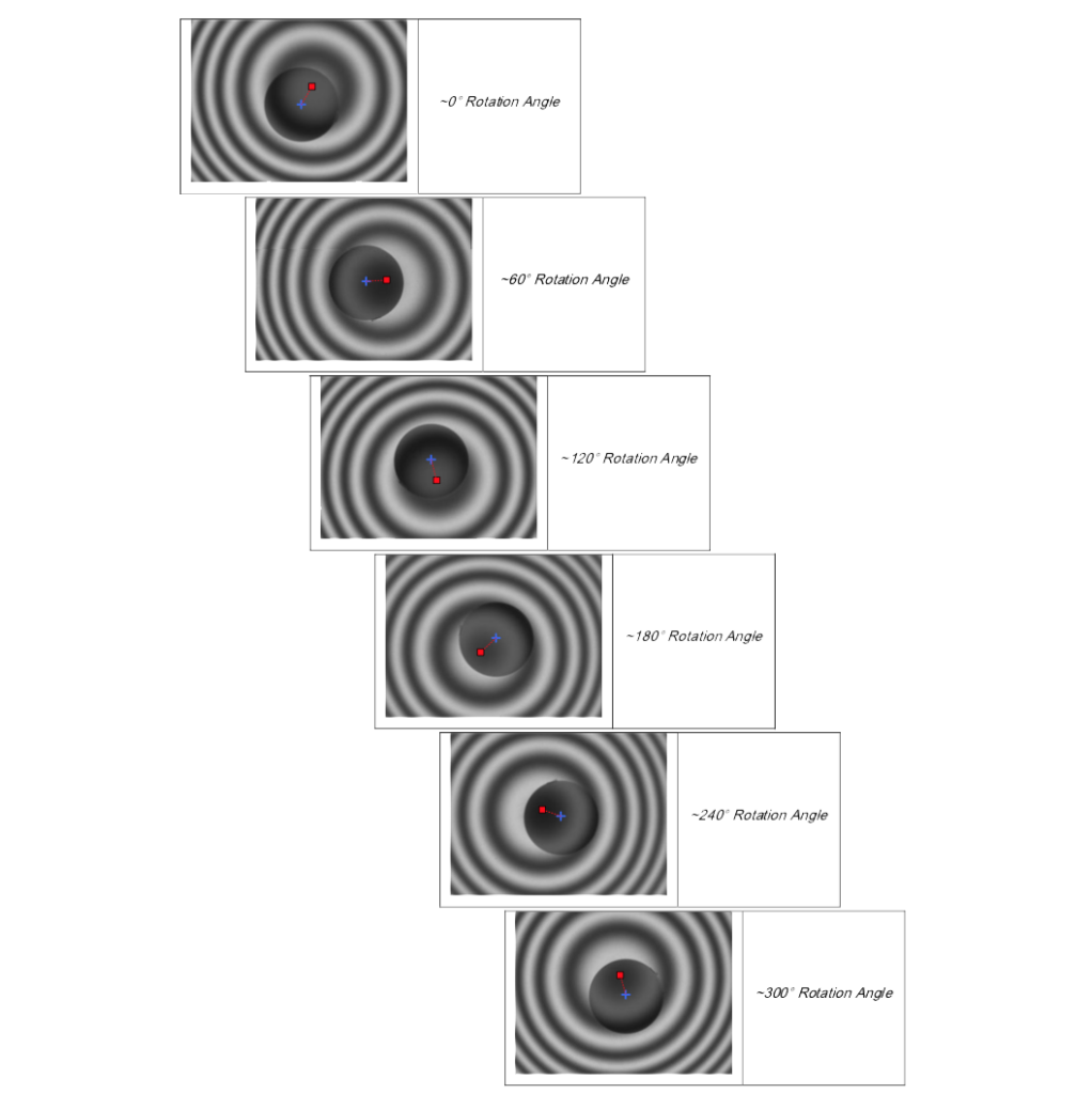
Fig. 9: Interferometric endface images with different rotation angles
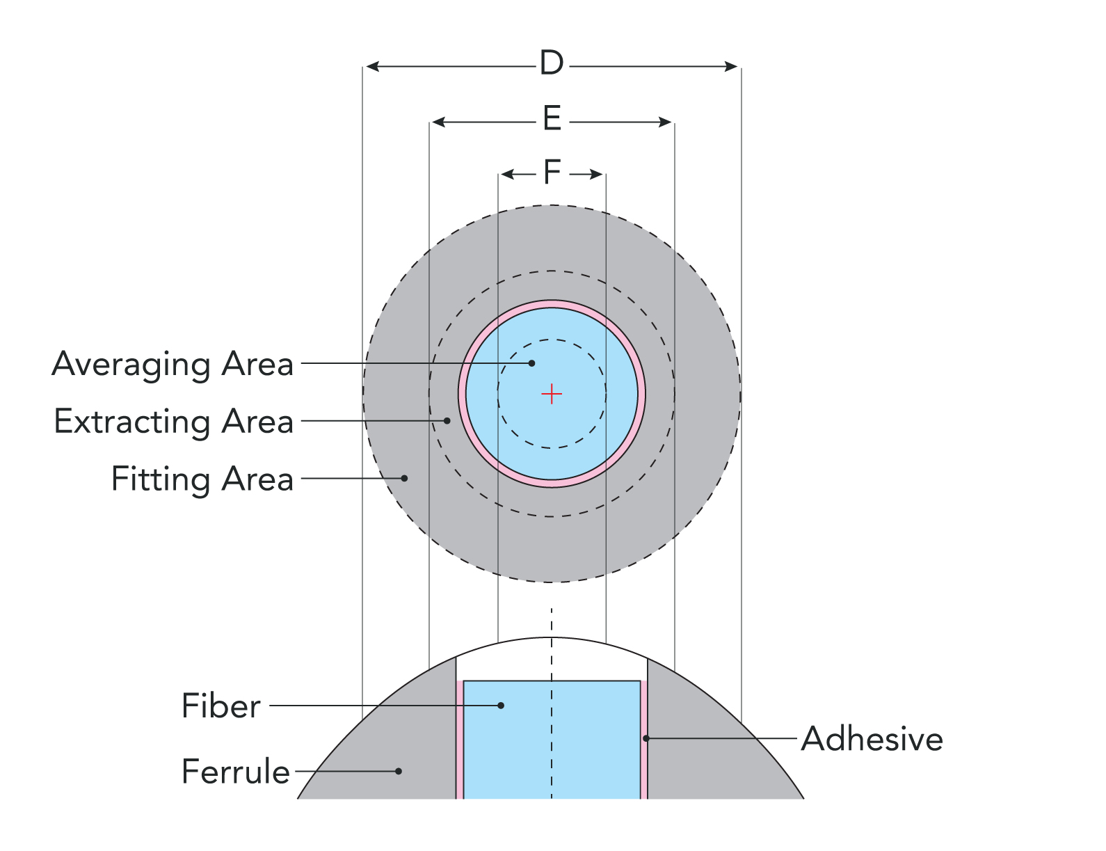
The center of the fiber is designated with a blue “+” and the center of the fringe pattern (which is the apex of the polish) is designated with a red square. The length of the red dashed line is the Linear Apex Offset and it stays the same length as the ferrule is rotated.
As shown in the following section, this same rotation performed on an APC ferrule gives very different results.
Rotation of a PC Ferrule
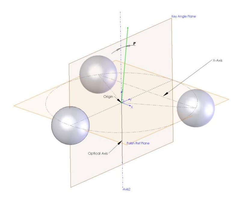
Because of a physical limitation of interferometry, the ferrule axis (green dashed line) of angle polished fiber optic connectors must be held at the polish angle relative to the interferometer axis (red dashed line) in order to properly measure the endface geometry.
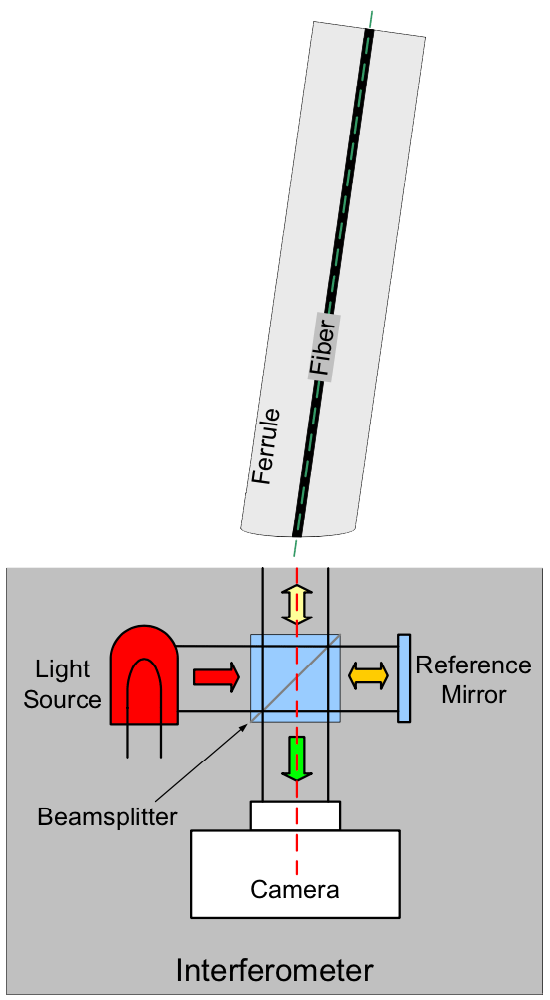
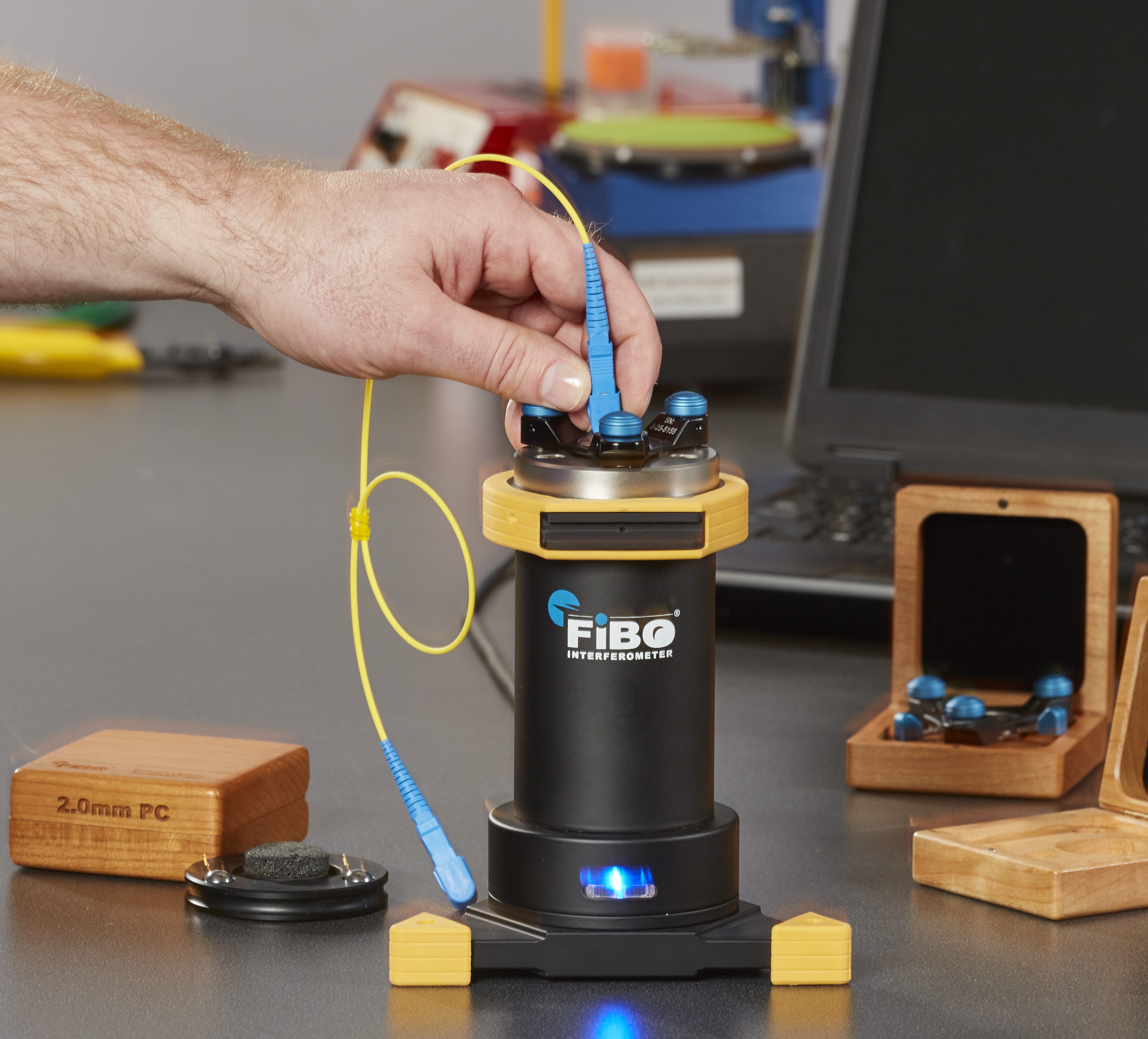
Fig. 10: The interferometer configuration for measuring the endface of an APC connector (note the ferrule tilted at 8 degrees).
The Radius of Curvature, Linear Apex Offset and Fiber Undercut/Protrusion are then measured in the same manner used for PC connectors.
According to TIA-455-218, the Angular Apex Offset can then be divided into two orthogonal angles: Angle of Polish Error and Key Angle Offset Error.
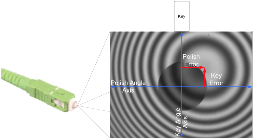
Fig. 11: Relationship between the endface of an APC connector and the Polish and Key error.
The Angle of Polish Error is the amount of Angular Apex Offset in the direction perpendicular to the key position of the connector. Any angle errors in the polish angle or the fixturing in this perpendicular direction will directly influence the Angle of Polish Error and in turn the Linear Apex Offset.
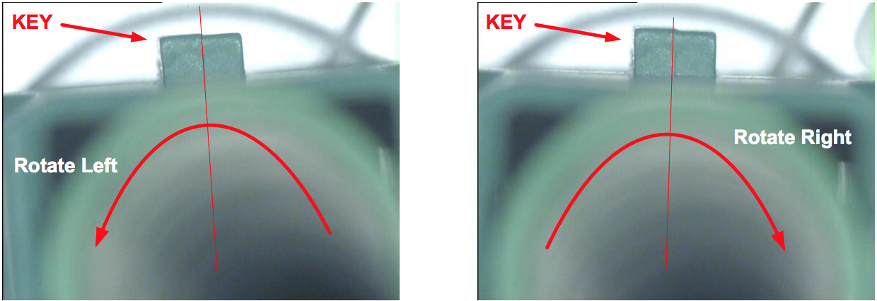
The Key Angle Offset Error is the amount of Angular Apex Offset in the direction parallel to the key position of the connector. Errors in the connector’s key position are equivalent to rotating the connector about the axis of the connector’s ferrule (green dashed line) as in the following diagram:
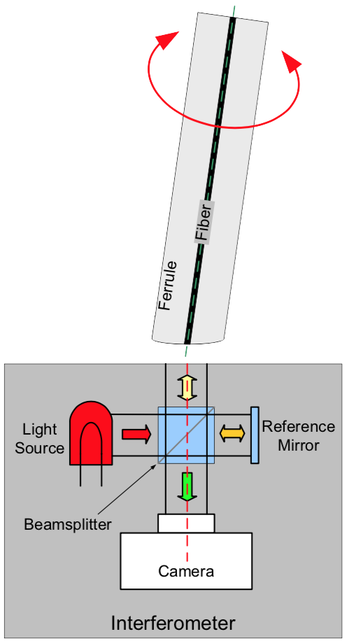
Fig. 12: APC ferrule rotation indicated by red arrow.
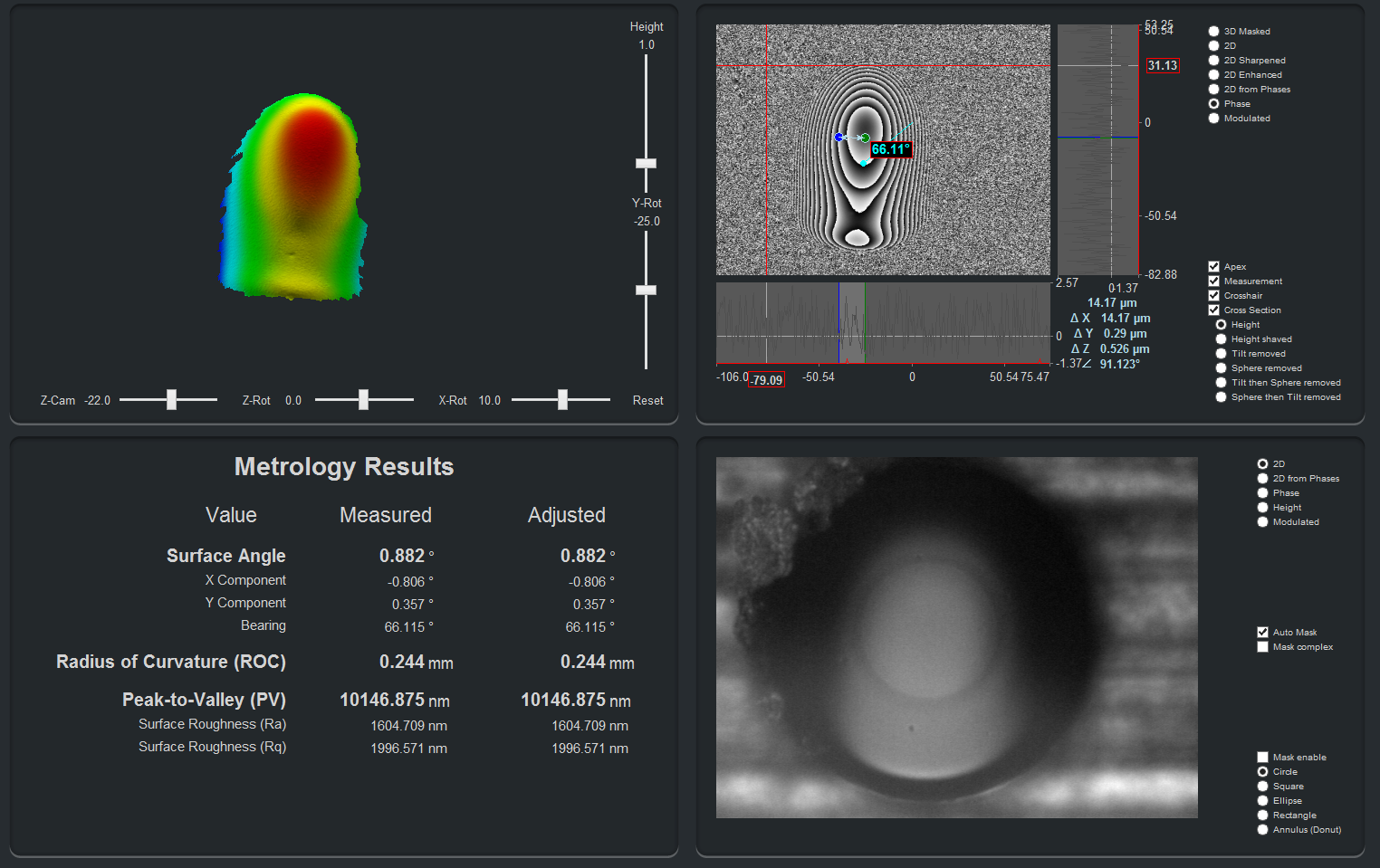
The following fringe images of a connector endface illustrate how the center of the interferometric fringe pattern moves as an APC ferrule (tilted at 8 degrees to the interferometer axis) is rotated. The ferrule is rotated in its holder from out of alignment, through correct key angle alignment and then out of alignment again (the connector key is at the top of the images). The center of the fiber is designated with a blue “+” and the center of the fringe pattern is designated with a red square.
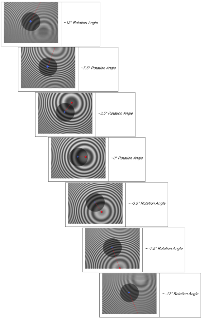
Fig. 13: Interferometric Endface Images with Different Key Orientation Angles
The center of the circular fringes corresponds to the peak of the endface’s spherical shape. As the ferrule is rotated, the distance from the center of the fringe pattern to the center of the ferrule is the Linear Apex Offset (red dashed line) which can be divided into Polish Angle Offset Error (horizontal) and Key Angle Offset Error (vertical). When the center of the fringe pattern is aligned horizontally to the center of the fiber, there is zero Key Orientation Angle (KOA) Error, and the ferrule is properly rotated to align with the key of the connector.
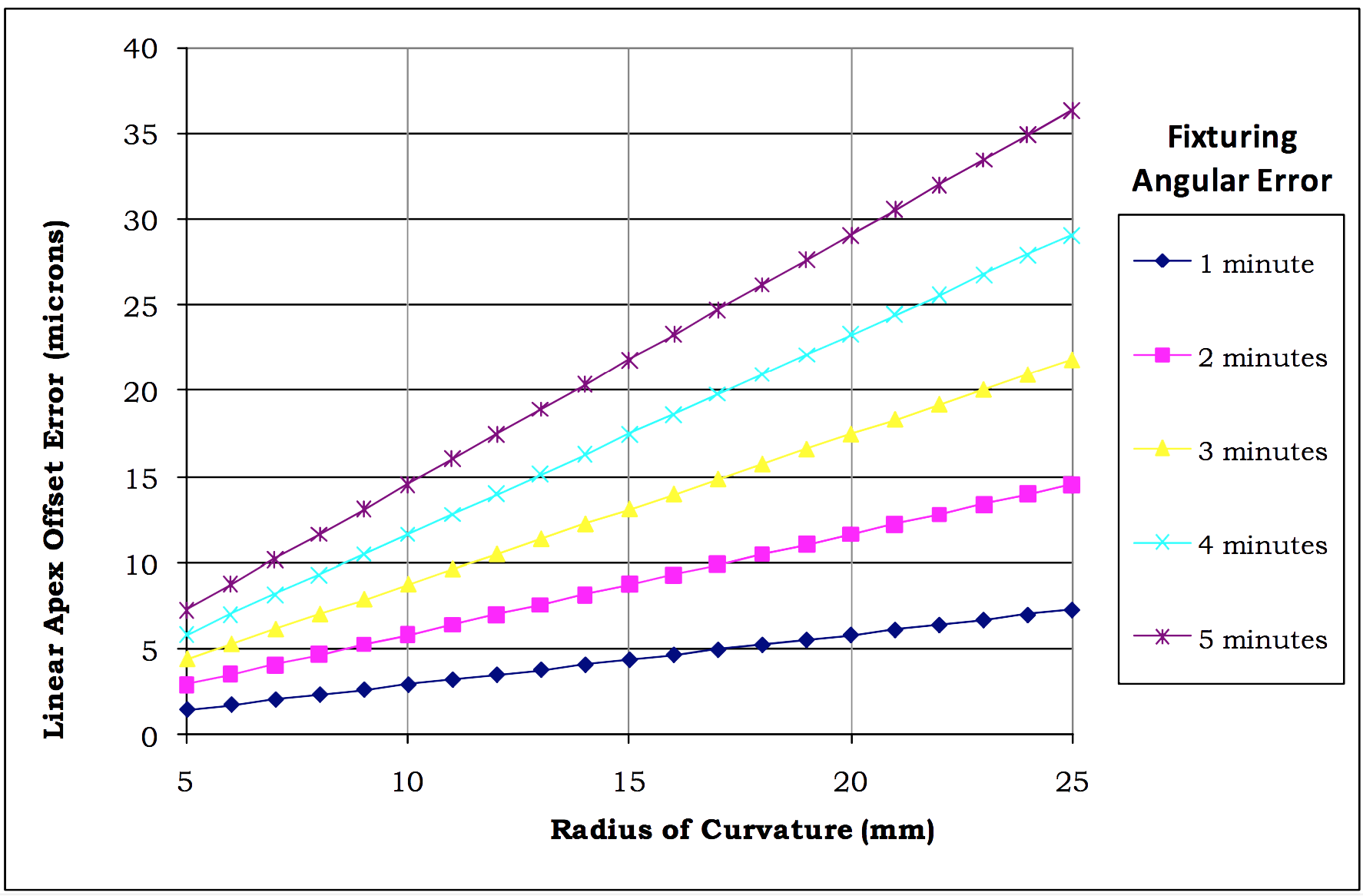
Because the ferrule is held at its polish angle relative to the interferometric measurement device, this Key Orientation Angle Error does not directly correspond to changes in the Key Angle Offset Error, but are scaled. The objective is to determine this relationship theoretically.