ENDFACE TESTING
Made by Promet Optics

The 3 point kinematic interface system used in FiBO Interferometers ensures highly accurate, repeatable and reproducible endface geometry measurements that do not require re-calibration when changing between adapters PC or APC. A discussion about why the kinematic interface matters is below.
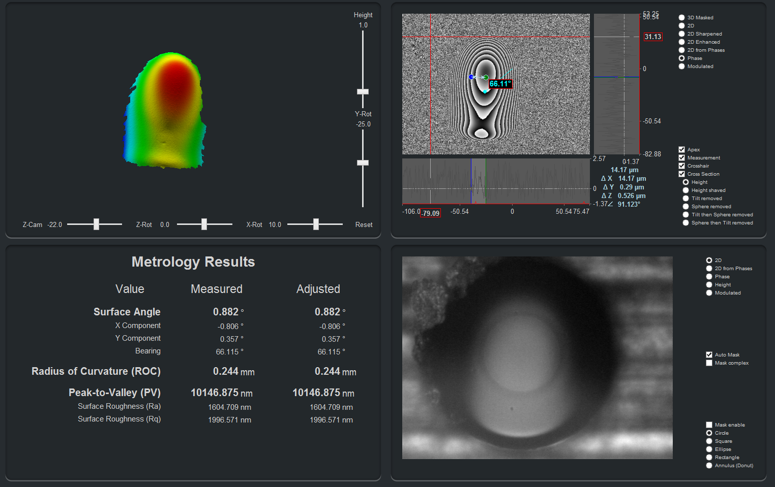
How to measure the PC & APC terminations using the FiBO 200 is shown.
A common misconception in metrology is that specifications and performance of an instrument are what dictate the quality of data obtained. This may be the case for some types of metrology but for any sort of surface profilometry, like fiber optic endface geometry, the quality of data obtained is highly dependent on how the part to be inspected is held or fixtured in reference to the instrument. Using high end, expensive instrumentation to measure a poorly held or referenced part will ultimately lead to poor measurement data.
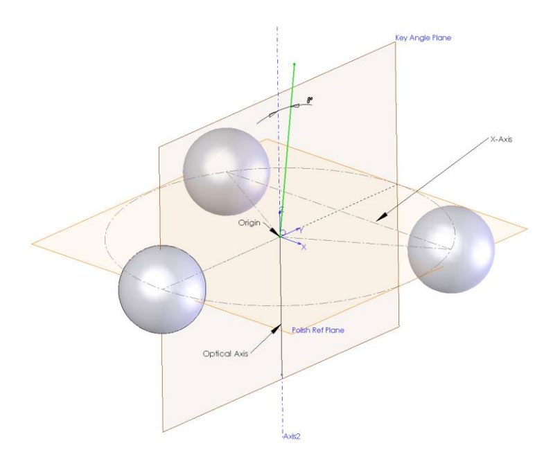
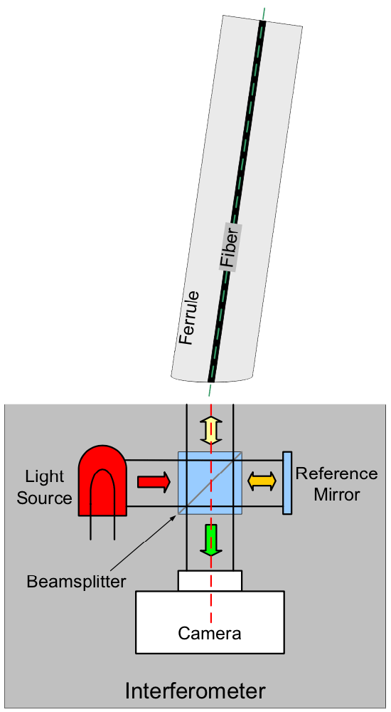
In the case of measuring endface geometry of fiber optic terminations, Promet Optics designed the FiBO Interferometer using a patented, unique method for solving this fixturing referencing challenge. FiBO uses a 3 point kinematic interface that can be manufactured to micron level mechanical reproducibility that insures the tip of the ferrule is as close to perpendicular to the optical axis as possible.
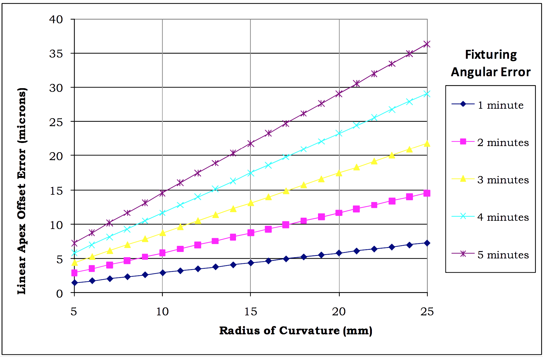
In simple terms this highly accurate kinematic interface is one of the steps to ensure the ferrule is not tilted during a measurement. A tilted ferrule will result in an excess apex offset, among other things. A few sources of this potential tilt error are explored.
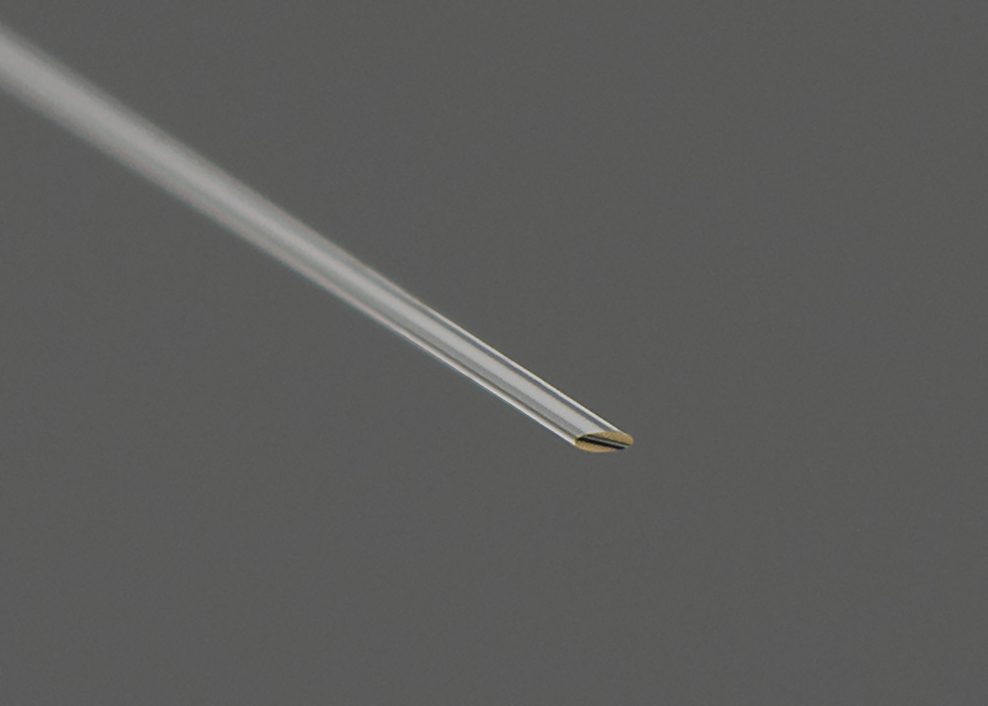
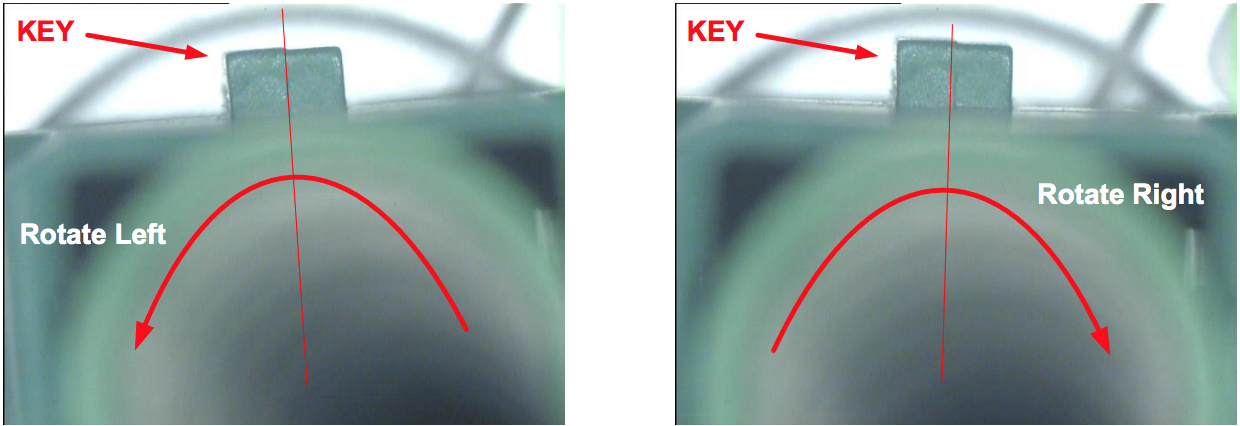
The simplest source of tilt error to notice is the ferrule tilted in relation to the interferometer and the adapter. This is not much of an issue with connectors, as the body provides rigidity and surface area to hold. Bare ferrules, like MIL style termini, are more difficult as there is less surface area. FiBO ferrule adapters use a clamping feature to hold the ferrule in place. For reference, 1.25 mm bare ferrules will tend to exhibit more apex offset variability than a 2.5 mm ferrule because there is less surface area to clamp onto.
If the adapter itself is tilted in relation to the interferometer, this can be another source of tilt error. The FiBO Interferometer adapters are aligned at the factory using high precision optical alignment techniques to minimize this potential tilt. These alignment techniques also allow highly accurate APC adapters to be manufactured at 8 degrees. Because both PC & APC adapters are aligned to the kinematic interface, not the interferometer itself, FiBO does not need to be re-calibrated when changing between different adapters.
Like the adapters mentioned above, the interferometer is also aligned to the kinematic interface. Because of this, an additional source of tilt can exist inside the interferometer. FiBO addresses this potential source of error by calibrating out any residual tilt of the interferometer’s optical axis in relation to the kinematic interface during the 4 step calibration process.