ENDFACE TESTING
Made by Promet Optics

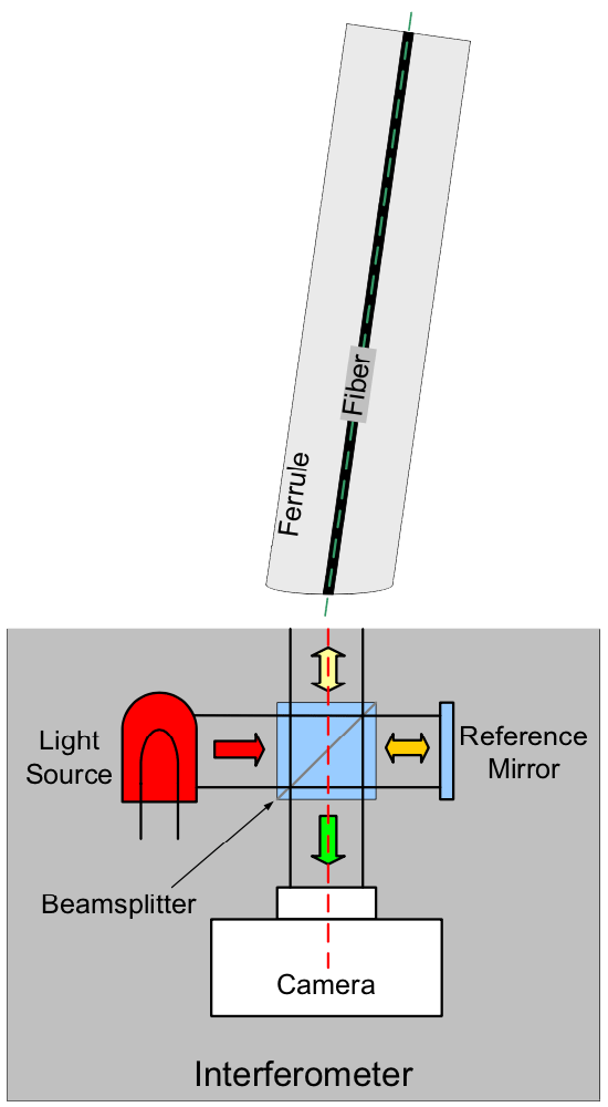
This is the 3rd of a 3 part post from the white paper entitled “Fiber Optic 3D Metrology”. We will define and lay out the necessity of measuring endface geometry as well as a conceptual overview of Michelson Interferometry, which is used to measure it.
Standards such as TIA-455-218 (FOTP-218), IEC 61300-3-16, IEC 61300-3-17 and IEC 61300-3-23 describe how to measure the three-dimensional properties of a single fiber optic connector endface. The three main properties measured are:
- radius of curvature
- apex offset (offset of the polish relative to the center of the fiber)
- fiber height (relative to the ferrule surface)
Radius of Curvature
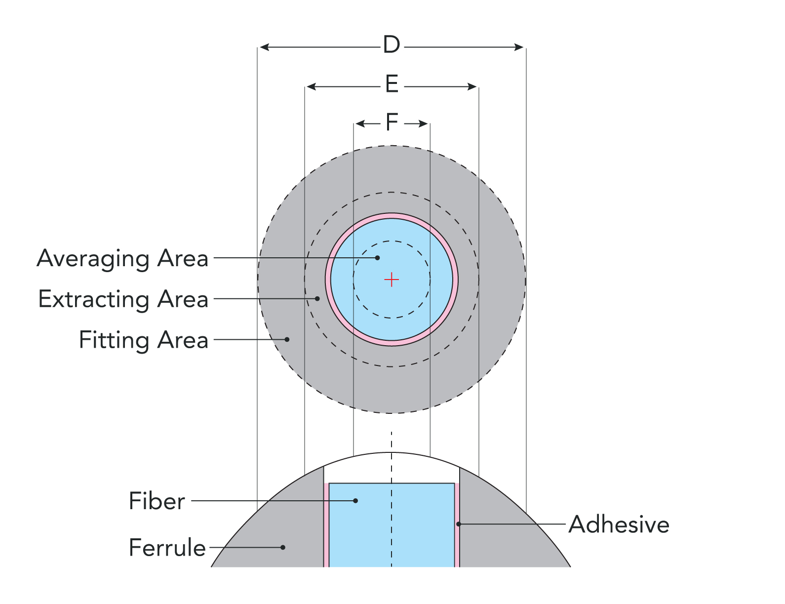
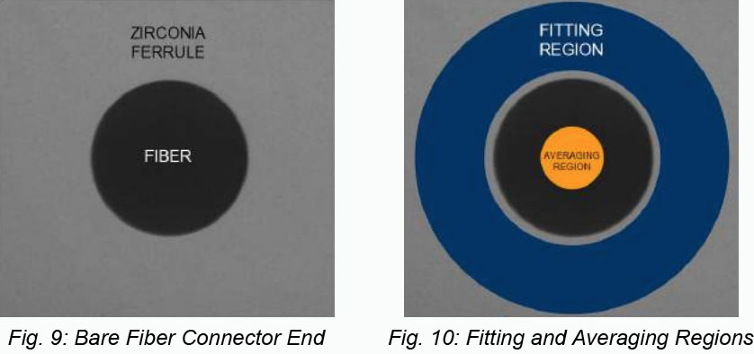
The first step given in these standards is to obtain a three-dimensional map of the connector surface. FiBO® obtains this map with the technique of phaseshifting interferometry described above. The next step is to numerically fit an ideal sphere to the measured data. Not all of the data is used for this fitting. Only a donut-shaped slice of the ferrule called the contact zone (or fitting region) is used. The standards recommend using a slice that has an outer diameter of 250 microns and an inner diameter of 140 microns. This fitting region is used because the endface can be aspherical and using the defined region for fitting achieves better agreement between measurements by different interferometers. The radius of this fitted sphere is then reported as the measured radius of curvature. A typical acceptable radius of curvature range is between 7 and 25 millimeters. Figures 9 and 10 show a connector endface with, and without, the fitting region displayed.
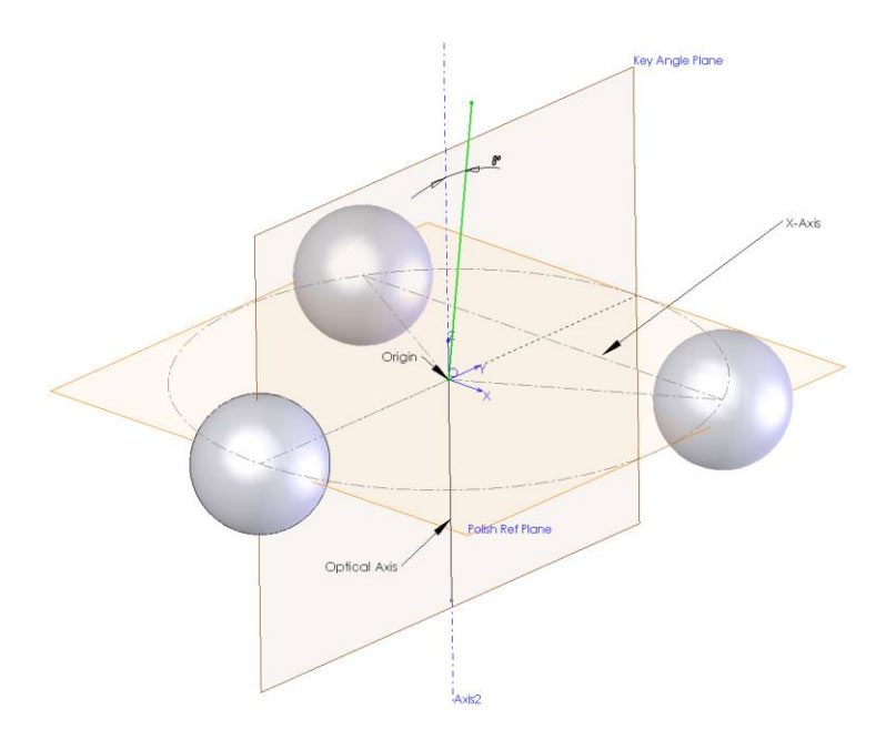
Apex Offset
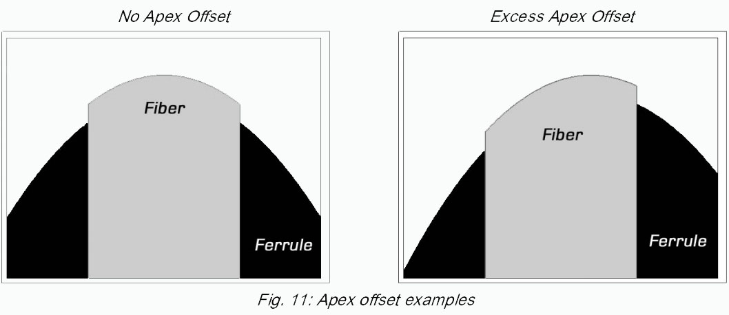
The linear distance in microns between the center of the fiber and the fitted sphere in the plane of the image is reported as linear apex offset. The exaggerated cross-sectional diagrams of a connector endface in Figure 11 illustrate a connector with no apex offset (left) and with excess apex offset (right).
Fiber Height
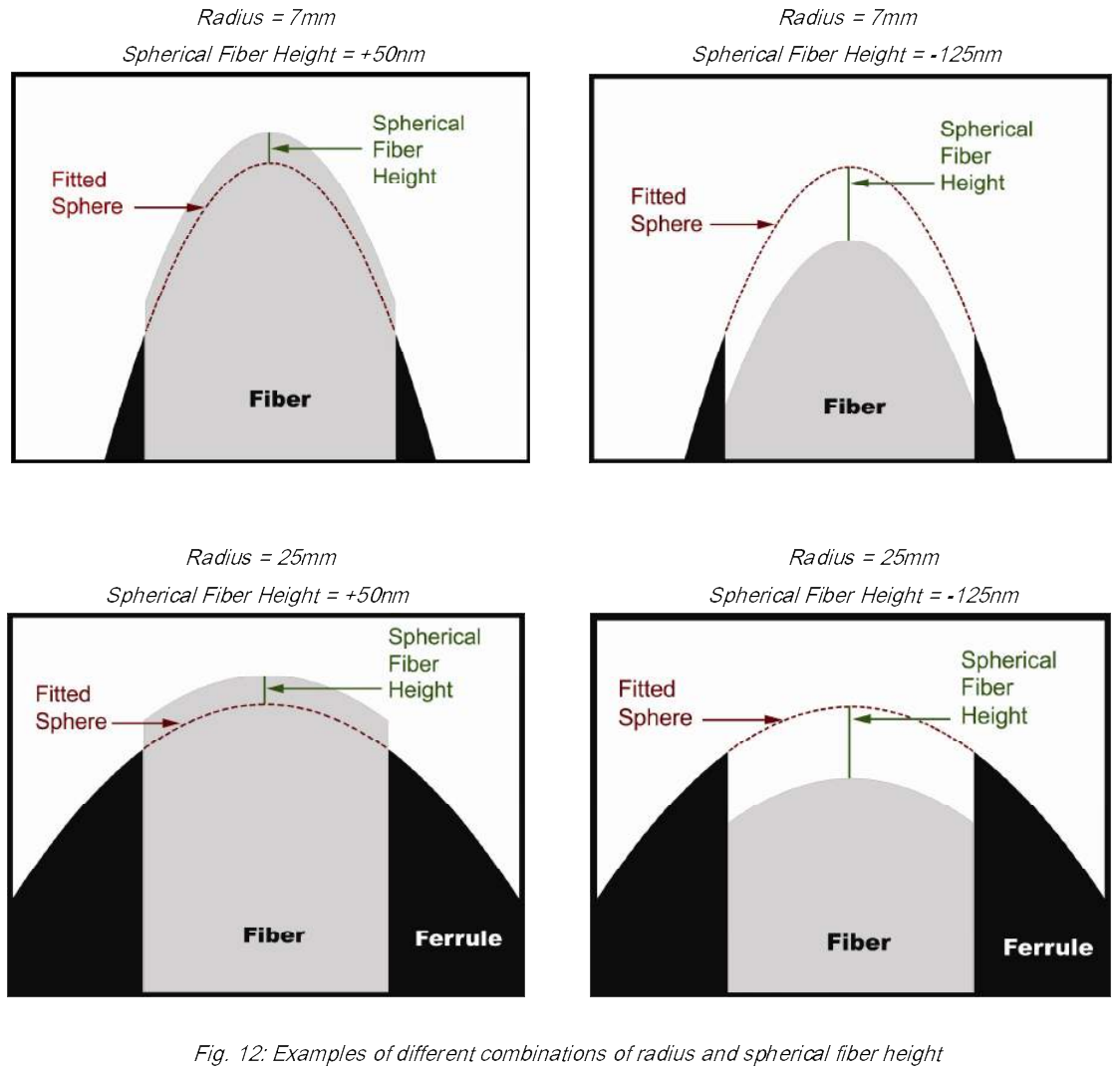
Fiber height, in nanometers, is calculated by first subtracting the fitted sphere from the measured data. The heights in a central area of the fiber, called the averaging area, are averaged together. The diameter of this circle, centered on the center of the fiber, is typically 50 microns. The average height in the contact zone is then subtracted from this average fiber height. This difference is called the spherical fiber height. We define spherical fiber height as being positive when the fiber protrudes above the fitted sphere. A typical range for fiber height is from -125 to +50 nanometers.
The images (not-to-scale) in Figure 12 illustrate examples of cross-sections of different combinations of fiber radius and spherical fiber height. The gray area is the fiber, the black area is the ferrule, the dashed red line is the fitted sphere, and the solid green line is the spherical fiber height distance.