ENDFACE TESTING
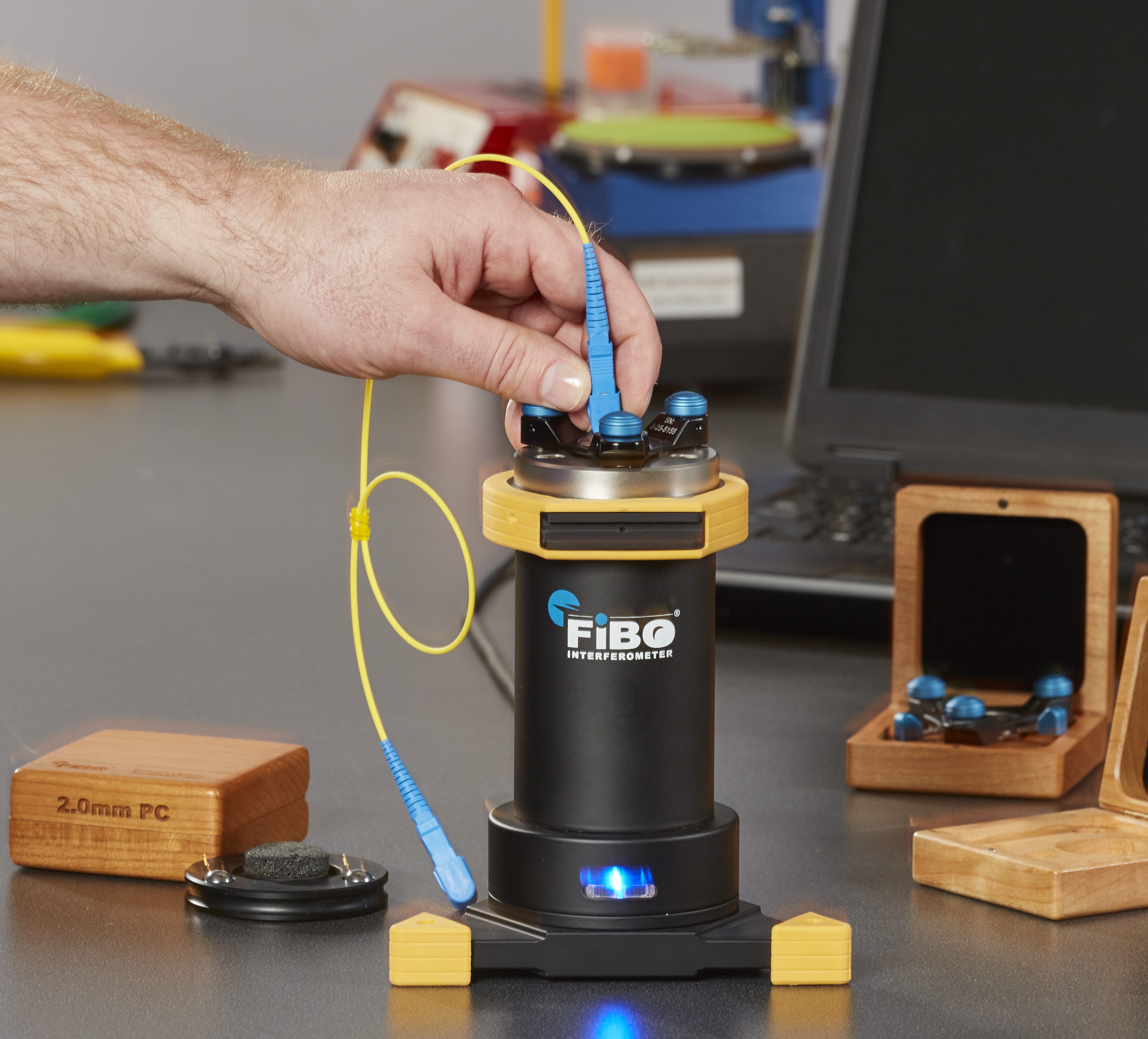
Made by Promet Optics

This is the 1st of a 3 part post from the white paper entitled “Fiber Optic 3D Metrology”. We will define and lay out the necessity of measuring endface geometry as well as a conceptual overview of Michelson Interferometry, which is used to measure it.
Introduction to Fiber Optic Connector 3D Metrology
In theory, higher bit rate fiber optic systems tighten link-loss budgets. A vital element of linkloss budgets is the loss affiliated with ferrule to ferrule contact between connectors. Connector losses are usually determined by implementing insertion loss and reflection loss tests. The outcomes of these tests are relative to a reference connector that is used to carry out the tests.
The Impact of a Poor Reference Connector
The endface geometry of the reference connector and connector under test has a direct effect on the results of these loss measurements. Using a reference connector that has improper endface geometry can yield different – and deceptive – loss measurements. If connectors are used in a network that have good loss performance characterized with faulty reference connectors, they might not offer good results when attached to connectors that were tested with a correct reference. The network performance will be impaired.
To clarify this point, Figure 1 is an example of exaggerated cross-sections of two connector endfaces making contact. The images on the left and right show connectors with distinctive geometries making good, low-loss contact at the center of the two fibers (the colored lines in the center of the images). The third image, in the center, takes a connector from each of the other two images and proves that contact would be poor at best.
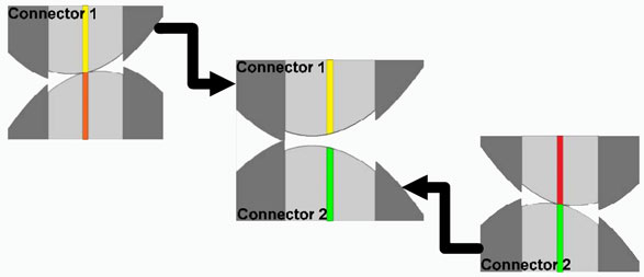
Three different connector endface interfaces, where the left and right one have good contact and the middle one has poor contact.
Because the reference connector requires correct endface geometry to secure a good connection, it follows that every connector in the network needs to have correct endface geometry as well.
The FOCIS Standards for Guidance
Furthermore, there is a series of TIA/EIA (Telecommunication Industry Association/Electronic Industries Alliance) standards called the Fiber Optic Connector Intermateability Standards – or FOCIS – that define the mechanical properties of numerous connector styles. The objective of these standards is to guarantee that connectors made to specification will reach a common level of performance. However, nearly all of these standards only mention an advised range for the radius of curvature for the geometry of the ferrule endface and do not mention other important endface geometrical parameters. Abiding by to a FOCIS alone will not guarantee a robust connection.